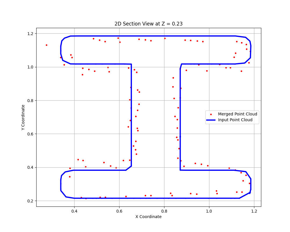
XY Cross-section comparing our compiled scan with an ideal STL
Aligned 3D Reconstructed Scan with an ideal model
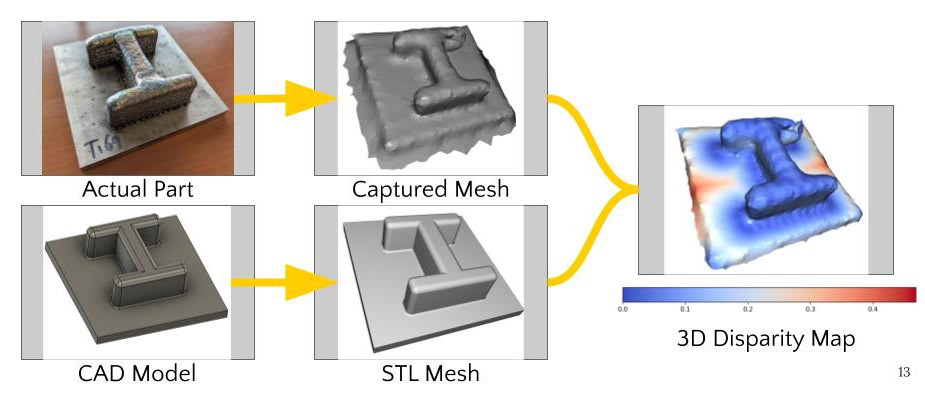
3D View of a generated disparity map

Computer Vision for Engineers: Written in Python, with the Open3D and Matplotlib libraries. Link to Github
As a team of 4 we aimed to create a defect detecting program using 3D reconstruction methods learned throughout the course. The program takes in a set of point clouds taken from scans off a physical part (We used an Intel Realsense D405 short-range stereo depth sensor) as input; this is then stitched together using pose-graphs to obtain a full scan that we then mesh into a 3D model using simple Poisson surface reconstruction.
We create a defect map by comparing the displacement between our ideal STL model, and our manufactured part. This is done by aligning the 2 clouds using RANSAC and ICP methods for global and local optimization. A disparity map is then derived using the built-in KDTree lookup function.
The blue bands observed in our disparity map are a direct result of capturing the metal printing additive manufacturing method used to produce the part.
Project Goals
Alignment Attempts
Attempts at aligning our point cloud to the ideal model using RANSAC/ICP. Plenty of hours were spent refining their parameters to reduce these errors and converge to the best solution.